#include #include SoftwareSerial mySerial(0,1); // RX and TX pins
int PIN_RED = 9;
int PIN_GREEN = 10;
int PIN_BLUE = 11;
String RGB = "";
String RGB_Previous = "255.255.255";
String ON = "ON";
String OFF = "OFF";
boolean RGB_Completed = false;
void setup()
{
pinMode (PIN_RED, OUTPUT);
pinMode (PIN_GREEN, OUTPUT);
pinMode (PIN_BLUE, OUTPUT);
Serial.begin(9600);
mySerial.begin(9600);
RGB.reserve(30);
}
void loop()
{
while(mySerial.available())
{
char ReadChar = (char)mySerial.read();
if(ReadChar == ')')
{
RGB_Completed = true;
}else{
RGB += ReadChar;
}
}
if(RGB_Completed)
{
Serial.print("RGB:");
Serial.print(RGB);
Serial.print(" PreRGB:");
Serial.println(RGB_Previous);
if(RGB==ON)
{
RGB = RGB_Previous;
Light_RGB_LED();
}
else if(RGB==OFF)
{
RGB = "0.0.0";
Light_RGB_LED();
}else{
Light_RGB_LED();
RGB_Previous = RGB;
}
RGB = "";
RGB_Completed = false;
}
}
void Light_RGB_LED()
{
int SP1 = RGB.indexOf(' ');
int SP2 = RGB.indexOf(' ', SP1+1);
int SP3 = RGB.indexOf(' ', SP2+1);
String R = RGB.substring(0, SP1);
String G = RGB.substring(SP1+1, SP2);
String B = RGB.substring(SP2+1, SP3);
Serial.print("R=");
Serial.println( constrain(R.toInt(),0,255));
Serial.print("G=");
Serial.println(constrain(G.toInt(),0,255));
Serial.print("B=");
Serial.println( constrain(B.toInt(),0,255));
analogWrite(PIN_RED, (R.toInt()));//comment if colors are inverted
analogWrite(PIN_GREEN, (G.toInt()));//and uncomment part below.
analogWrite(PIN_BLUE, (B.toInt()));
// analogWrite(PIN_RED, (255-R.toInt()));//uncomment if colors are inverted
// analogWrite(PIN_GREEN, (255-G.toInt()));//and comment above part.
// analogWrite(PIN_BLUE, (255-B.toInt()));
}
Assignment 3
INTRODUCTION TO ELECTRONICS
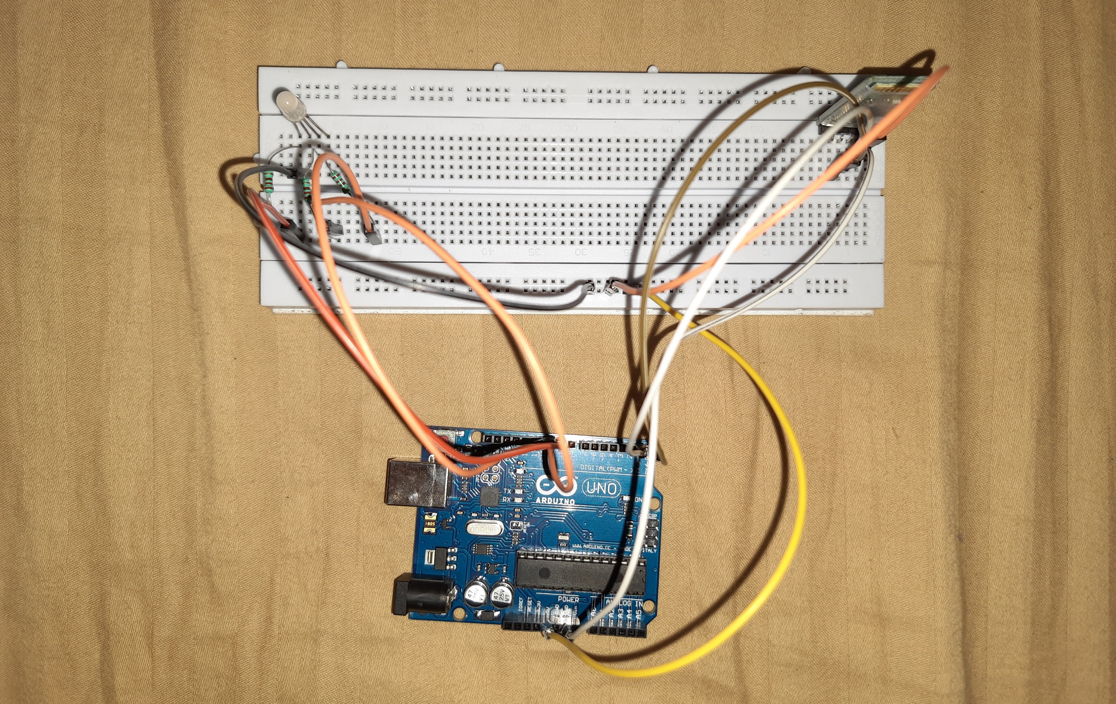
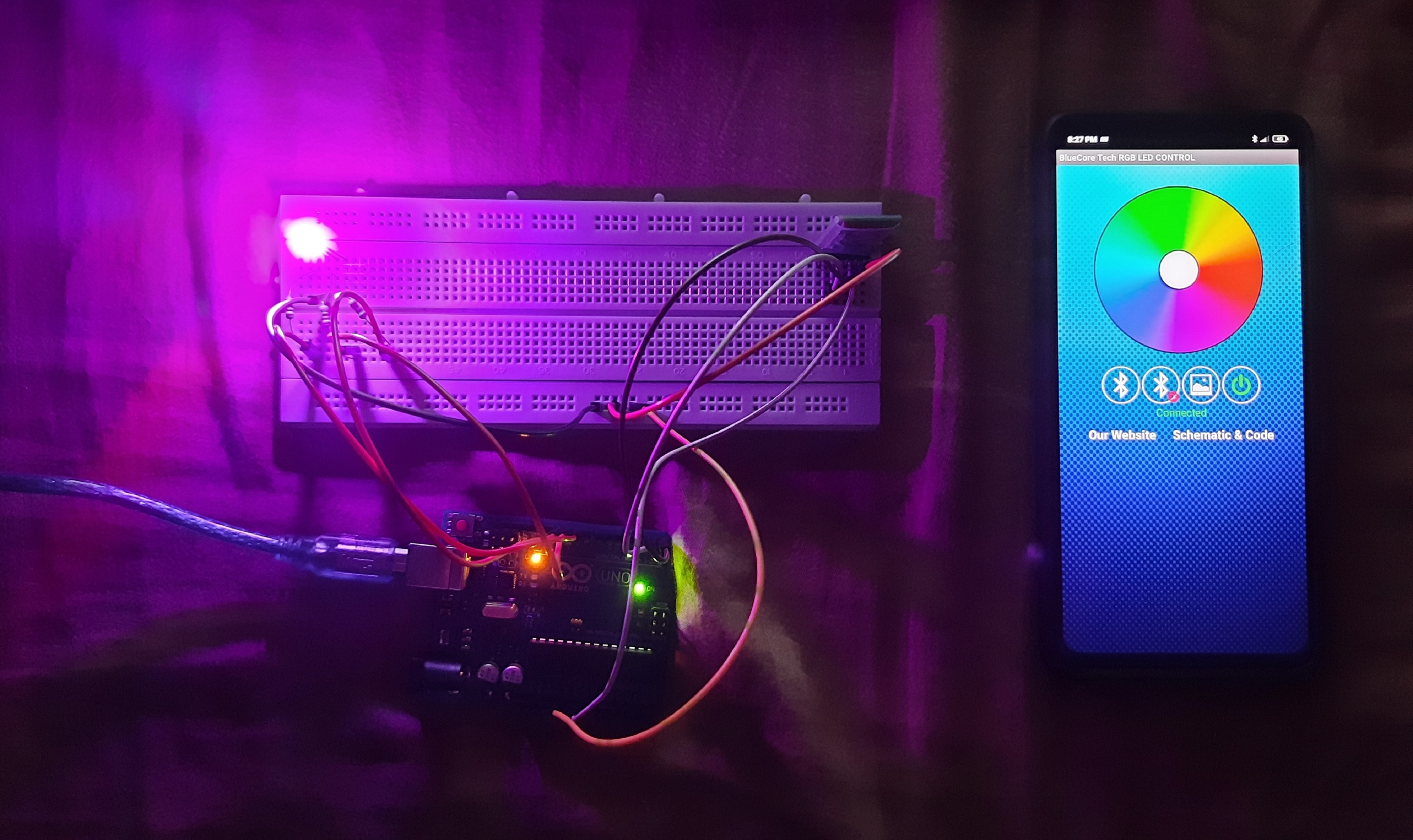
The objective of the assignment is to undrestand basic arduino programing for LED. Using the Arduino UNO and a Bluetooth chip, we have we a circuit that controls the colour using an android app. Metioned below are the components we need to build this setup:
Components Required
1. Arduino Uno
2. Bread Board
3. HC-05 Bluetooth module
4. 1 x Rgb LED
5. Jumper Wires
6. 3 x Resistors
Link for Android app - Arduino RGB Led Control
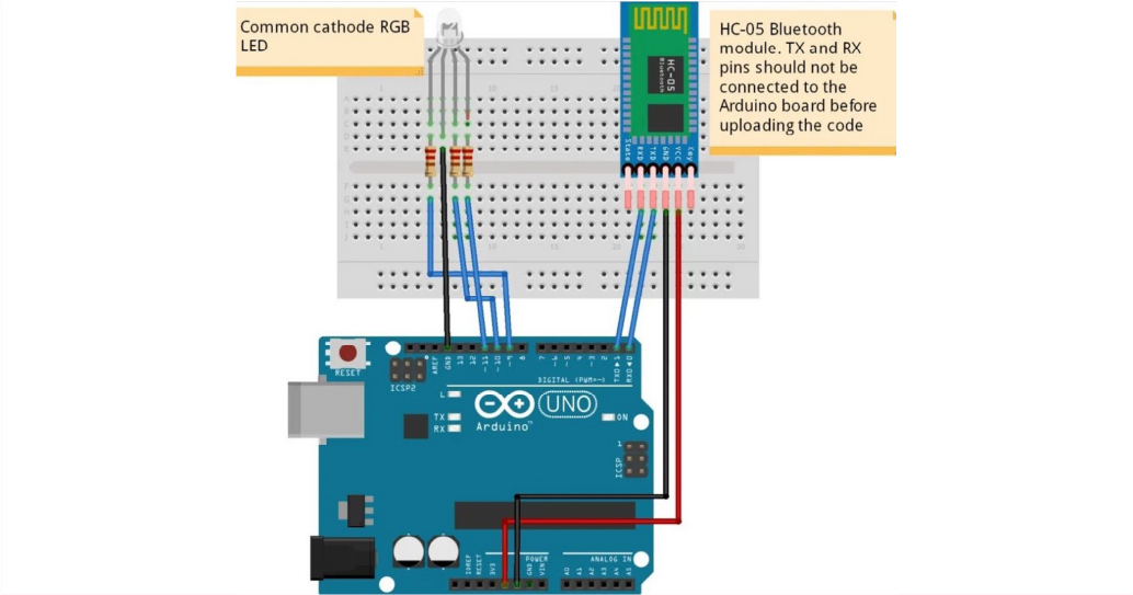
Schematic Diagram

Connections of HC-05 Bluetooth module
VCC – to VCC of Arduino.
GND – to GND of Arduino.
RX – to digital pin 0(TX pin) of Arduino.
TX – to digital pin 1(RX pin) of Arduino.

Note:
i). Connect RX and TX pins after uploading the code
ii). The terminals of the RGB LED should be connected to PWM pins of the Arduino.
Code

